A STEP file carries a part's shape but not how it was built. A native CAD file carries the history, but only its own vendor can read it. featuretree keeps a small format in between. We've written that format up as a specification, with measurements of how well each CAD system rebuilds it.
The paper is on Zenodo. This post covers the same ground with less formality.
Why a format at all
More and more parts are written by programs and by language-model agents. Most of that output is either bare geometry or code for one CAD kernel. Neither is much use to the person who has to review the part. They want to open it in the CAD system they already know, see the steps it was built from, change one dimension, and hand it back.
Every history-based CAD system already shows that list of steps. FreeCAD calls it the model tree, Onshape the feature list, Fusion the timeline, SolidWorks the FeatureManager tree. The names differ and the files are incompatible, but the idea is the same. Our format is that list with the vendor taken out: something an agent can write, each CAD system can rebuild as its own native features, and an edit made in any of them can be read back into.
Which features belong in such a list is an old question. People have been cataloguing CAD features since the 1980s and nobody has a complete set. We haven't tried to produce one. We picked a small subset, measured how far it gets, and wrote down the rule for adding to it.
The format
A part is a JSON list of named features, in the order they're built. There are seven kinds: sketches (lines, arcs, circles), pad, pocket, fillet, revolve, and two kinds of placed cut, with draft angles on the extrusions.
{"name": "plate", "features": [
  {"kind": "sketch", "name": "outline", "plane": "XY",
   "polys": [[[-20,-15],[20,-15,0.4142],[20,15],[-20,15]]]},
  {"kind": "pad", "name": "body", "sketch": "outline", "length": 10},
  {"kind": "sketch", "name": "recess_sk",
   "on": {"face_of": "body", "side": "top"}, "circles": [[0, 0, 6]]},
  {"kind": "pocket", "name": "recess", "sketch": "recess_sk",
   "through": false, "length": 4},
  {"kind": "fillet", "name": "round", "radius": 1,
   "select": {"circles": "top_outer"}}]}
Two decisions matter most.
- Features refer to geometry by query, never by id. The recess is sketched on "the top face of body", and the fillet goes on "the largest circle on top". Each CAD system finds that face or edge again every time it rebuilds. A CAD kernel's internal ids change when the part changes, which is why files that store them break.
- It is data, not code. There's nothing to execute, so a program can check it before anything is built. A validator,
ir.validate(), checks the rules every backend is allowed to assume.
What each feature becomes
| In the format | FreeCAD | Onshape | Fusion, SolidWorks | Reads back |
|---|---|---|---|---|
| sketch | Sketch | Sketch | Sketch | circle radii |
| pad | Pad | Extrude (add) | Extrude (join), Boss-Extrude | length |
| Extrude (remove) | Extrude (cut), Cut-Extrude | length | ||
| fillet | Fillet | Fillet | Fillet | radius |
| revolve | Revolution | Revolve | Revolve | angle |
| placed cut | plane, sketch, Pocket | plane, sketch, Extrude (remove) | plane, sketch, cut | depth |
Each feature keeps its name in the target's tree. That name is the only thing used to match an edit on the way back.
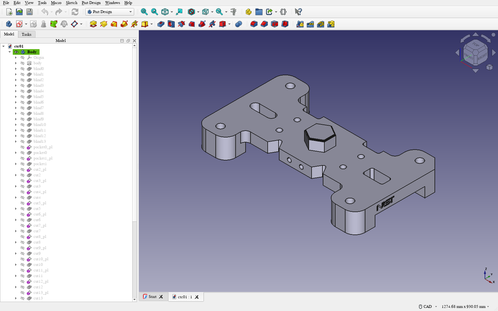
One of the eleven test parts, NIST CTC-01, open in FreeCAD. The Model panel on the left is the format's feature list as native FreeCAD features, with the same names: body, blind0, cut3. Each placed cut shows up as a plane and a pocket. These are the entries we edited in the round-trip test below.
FreeCAD and Onshape are driven from outside and we've measured both. build123d, a Python CAD library, is the reference that everything else is compared with. Fusion and SolidWorks can only be scripted from inside the program, so for those we generate a script. Those two scripts have not been run yet, and we report no results for them.
We also looked for a way to write a SolidWorks file without owning SolidWorks. The open-source library we use to read SolidWorks files lists them as something it can write too. In practice its writer declines even a plain box, and none of its forks change that. So the open route reads SolidWorks files but can't write them yet.
How we check
Every system is checked the same way. The part is exported to STEP and compared with the reference build, by volume and by overlap (IoU). It passes at 99.5% overlap and volume within 0.5%. Each backend also records the volume after every feature, so when two of them disagree we can see which feature caused it.
Results
The test set is the eleven parts of NIST's CAD test suite, as feature trees of 2 to 144 features that featuretree recovered from the STEP files.
- FreeCAD matches the reference on 10 of the 11. The eleventh breaks one of the format's rules, described below.
- Onshape has run on 3 and passes 1. On the second it built 53 of 54 features and landed just under the bar. On the third, the largest, it built 93 of 144 and the result is far off; ten stacked pads fail there and we don't yet know why. The other eight haven't run. Onshape's free plan allows about 1,500 API calls a day, and our emitter uses several per feature, so the largest part took a whole day's allowance.
- On small parts written to exercise each feature, Onshape matched to three decimals, apart from one pocket that removed 4.175 mm³ too much. We haven't explained that either.
Changing a dimension and getting it back
This is the loop the format is for, so we measured it. On ten parts we took up to six dimensions each, 46 in all. One at a time, we set a dimension to 1.1 times its value in the FreeCAD file, as someone would in the GUI. Then we read every parameter back into the format and rebuilt the part from the format with the reference.
43 of 46 edits came back correctly. The first time we ran it, only 27 did. In 16 cases the edit never arrived: FreeCAD stores a placed cut as a Pocket and reports its depth as "length", our reader was looking for "depth", and the change was dropped without any error. The rebuilt part was simply the old part. That bug had been there since we first wrote the round trip. It's fixed now.
The three that still fail are all changes to the height of a part's base. In two, FreeCAD's rebuilt solid is invalid. In one, neither system produces a solid. We think it's because the recovered trees place later cuts at fixed coordinates instead of relative to the base, but we haven't confirmed that.
Only dimensions make the trip. If someone adds, deletes or reorders a feature in the CAD system, we don't read that back yet.
How much of a designer's vocabulary this covers
NIST also publishes the same parts as native SolidWorks files, with the original designers' feature trees inside. We counted the features they used: 240 across the eleven parts.
| Designer's feature | Count | In our format |
|---|---|---|
| extrude | 85 | its own kind |
| hole | 63 | shape only, as a cut |
| fillet | 37 | its own kind |
| pattern | 27 | shape only, one cut per instance |
| draft | 11 | shape only, as a taper |
| chamfer | 10 | shape only, as a cut |
| revolve | 4 | its own kind |
| shell, rib, combine | 3 | shape only, or nothing |
About half (126 of 240) have a kind of their own. For most of the rest we can hold the shape but not the meaning. A designer's single "pattern of twelve holes with a counterbore" arrives as twelve separate cuts. The geometry is right, but nobody can change twelve to sixteen by editing one number.
That table is also the to-do list. Hole, pattern and chamfer account for 100 of the 114 features without a kind. Adding those three would take coverage from 52% to 94% on these parts. Eleven parts from one test suite is a small sample, so we hold those percentages loosely.
The rule for adding a feature
Several of the bugs below came from a feature whose meaning we hadn't pinned down. So a new kind goes in only when:
- its meaning is written down without reference to any one CAD kernel, including every sign and direction;
- the validator checks what a backend may assume about it;
- the reference builds it, and a second system on a different kernel agrees at that feature;
- there's a native feature of the same meaning in each target, or we say plainly that there isn't;
- its dimensions survive the edit round trip.
What running them against each other found
No single backend reported any of these problems. Comparing backends found six:
- The reference itself was wrong. A pad from a bottom face at z = 0 grew upward into the part. Onshape disagreed on the first such feature. It's fixed, and none of our published results change.
- FreeCAD kept one solid. A sketch with several separate outlines padded only one of them, halving the part.
- Loops in one sketch must not touch. The format had never said so. One system accepted touching loops and another rejected them.
- A nearly flat arc is a straight line. One part had arcs with a radius of about two kilometres, and FreeCAD's sketch solver failed on them.
- Onshape's draft direction was opposite to our first guess. A tapered boss grew where it should have shrunk.
- Failure behaviour differs. A cut that removes nothing is an error in Onshape and silently does nothing elsewhere.
Reading native files back
We decoded each of NIST's SolidWorks files to STEP twice, with Onshape's importer and with the open-source decoder, and compared both with NIST's own STEP. Onshape matched on all 11. The open decoder matched on 1, and four of its wrong parts passed its own checks. One decoder is not enough. We now take geometry from the commercial importer and the feature history from the open one, and we've reported the failures upstream.
What's not new
Neutral feature exchange between CAD systems goes back to the macro-parametric work of the early 2000s, and a closely related system, CADIR, appeared in August. We don't claim to be first. What we're adding is an open spec, an MIT implementation, Onshape as a target, and measurements anyone can rerun.
What's next
- Hole, pattern and chamfer as kinds of their own.
- Fewer API calls per feature in the Onshape backend, then the other eight parts.
- Reading back more than dimensions: features added or removed in the CAD system.
- Running the Fusion and SolidWorks scripts.
Who did what
We steered the design with Claude over many rounds, pushing on correctness, generality and performance. Claude wrote and debugged the code and ran the measurements.
Everything is in punkfab/featuretree, and every table in the paper is regenerated from the repo. Got a design that should open as an editable tree somewhere else? Start a project →