Update 2026-09-29: layered recognition and a stricter gate lifted average overlap from 65% to 97.6% on the same eleven parts. See the results post. The numbers below are as first published.
A STEP file imports into a parametric CAD system as one frozen lump. The design history is gone. There is no pad depth to change and no hole diameter to edit, only a boundary representation: faces, edges and surfaces. featuretree is a heuristic feature-recovery harness for that B-rep geometry. It proposes a feature tree of sketches, pads, pockets, revolves and cuts, then checks the proposal by rebuilding it and comparing the result against the input. A tree that passes can be emitted as a native, editable model in FreeCAD, Onshape or build123d.
The check is the point. Every recovery comes back VERIFIED, PARTIAL, or refused, and a PARTIAL tree is labelled as one. A silently wrong feature tree is worse than no tree, because you would edit it.
None of this is a new idea. Automatic feature recognition has been published since the early 1990s, and commercial CAD has shipped it for decades. What's missing is an open implementation you can call from code and point at FreeCAD or Onshape, neither of which recognises features on import. featuretree is that, plus an honest account of how well it works. The preprint says so up front, and its prior-art scan is in the repo.
How it works: heuristics propose, a rebuild decides
The core heuristic is that most machined and printed parts are a 2D profile swept along an axis, plus holes and pockets. So recovery is cross-sectional:
- Find candidate axes. Every face normal and cylinder axis is a candidate. Each one is scored by how many faces are inconsistent with a prism along it: angled walls, cross-holes, anything spherical or freeform.
- Read the profile. Rotate the best axes onto Z and slice. The section's outline becomes a sketch and a pad; its inner loops become through-holes; concave cylinders that stop short become blind holes. Parts that are bodies of revolution take a meridian section and a revolve instead.
- Recognise shells. Boxes, pans and enclosures aren't prisms along any axis. A stack of slices along each principal axis finds them: mostly rings, closed at one end. The outline is split into layers (flange, wall, lip), each a pad, drafted if its slices say so; the cavity is a drafted pocket and the floor's openings are cut straight from the floor slice.
- Carve the rest. If the base extrude doesn't match, what's left over is carved away feature by feature. Each leftover lump is itself a profile along its own axis — a floor pocket, a through-web window, a cross-hole — and is recognised and cut in turn.
- Rebuild and compare. The recovered tree is re-executed and compared with the input: volume within 0.5% and extents within 0.05 mm is VERIFIED; anything else is PARTIAL, with the residual reported. Several axes can look plausible, so featuretree builds a candidate per axis and the rebuild picks the winner. No heuristic score ever decides.
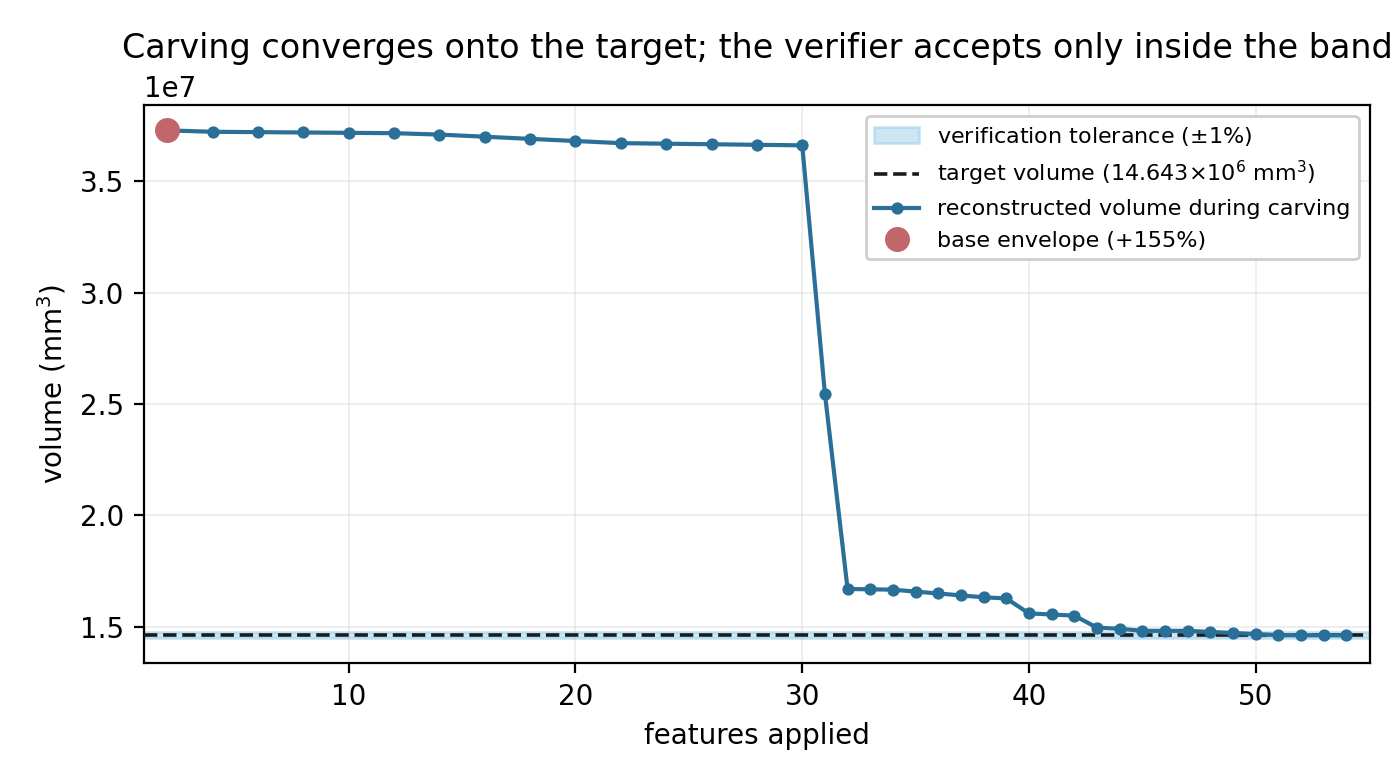
That carving loop on NIST CTC-01: a base extrude 155% too big, brought down into the tolerance band over 54 operations. The verifier accepts only inside the band.
The recovered tree refers to geometry symbolically — by feature name and query, never by a kernel's face or edge IDs — so the same tree drives FreeCAD, Onshape and build123d, and a human edit made in the GUI can be read back by name.
Coverage: every distinct NIST test geometry
We ran every distinct part geometry in the NIST MBE PMI test-case models: all five Combined Test Cases (CTC-01 to 05) and all six Fully-Toleranced Test Cases (FTC-06 to 11). We used NIST's "AP203 geometry only" exports, which are exact B-rep with no annotations. These are human-designed conformance parts, meant to be hard. That is the whole geometry set rather than a sample. NIST's five Simplified Test Cases reuse the FTC geometry with simpler annotations; everything NIST publishes that we did not run is listed after the results, with the reason.
Every part, every verification detail. A part is VERIFIED only if its rebuilt tree matches the input's volume to within 0.5% and its extents to within 0.05 mm; "Fails" says which test a PARTIAL part missed. IoU (intersection over union) is an independent check that uses no Boolean operations, measured with the recogniser's own transform undone, so it is an exact comparison with the input rather than a best guess at how to line the two up. The table is generated from the result files by paper/figures/corpus_table.py, so it cannot drift from the data.
| Part | Verdict | Fails | Vol. error | Extent error (mm) | IoU (%) | Features | Recovered as |
|---|---|---|---|---|---|---|---|
| CTC-01 | VERIFIED | — | 0.14% | 0.0 | 99.81 ± 0.07 | 54 | extrude Z · 14 pockets, 10 holes |
| CTC-02 | PARTIAL | both | 62.19% | 267.7 | 7.4 ± 0.4 | 64 | extrude Y · 2 regions |
| CTC-03 | PARTIAL | both | 41.46% | 132.5 | 36.1 ± 3.0 | 16 | extrude Y |
| CTC-04 | PARTIAL | both | 2.43% | 390.0 | 30.8 ± 0.5 | 270 | extrude Z |
| CTC-05 | PARTIAL | both | 51.80% | 349.2 | 14.5 ± 0.8 | 106 | extrude Z |
| FTC-06 | PARTIAL | both | 31.85% | 98.8 | 59.6 ± 0.6 | 44 | extrude Y · 17 pockets, 5 holes |
| FTC-07 | PARTIAL | extents | 0.09% | 1.5 | 95.5 ± 0.4 | 25 | drafted shell ∥Y (1.0°) · 3 outline layers · 9 pockets, 8 holes |
| FTC-08 | PARTIAL | volume | 3.56% | 0.0 | 95.9 ± 0.4 | 48 | shell ∥Z · 2 outline layers · 21 floor cutouts |
| FTC-09 | VERIFIED | — | 0.19% | 0.0 | 99.70 ± 0.05 | 80 | extrude Y |
| FTC-10 | PARTIAL | both | 20.80% | 18.0 | 76.0 ± 0.5 | 24 | extrude Z |
| FTC-11 | VERIFIED | — | 0.00% | 0.0 | 100.00 ± 0.00 | 2 | revolve |
- 11 of 11 parts yield an editable feature tree. None is refused.
- 3 of 11 are VERIFIED (one Combined, two Fully-Toleranced), each above 99.6% IoU with the input. FTC-11 is a two-feature revolve and should carry little weight.
- No incorrect tree was accepted. That is the property that makes the output safe to edit, and it holds on a measurement that uses no Boolean operations.
- The other 8 are PARTIAL: an editable tree for part of the geometry, labelled as such, ranging from 7% of the part (CTC-02) to 96% (FTC-08).
- Six of the eight PARTIAL parts fail both tests. FTC-07 now fails only on extents (its rim flares 1.5 mm wider than the recovered lip) and FTC-08 only on volume (3.6% short). CTC-04 is the reverse trap. It is within 2.43% on volume, but its extents are off by 390 mm and it overlaps its input by only 31%. Every PARTIAL recovery has less volume than its input: when featuretree falls short it leaves material out, it does not invent it.
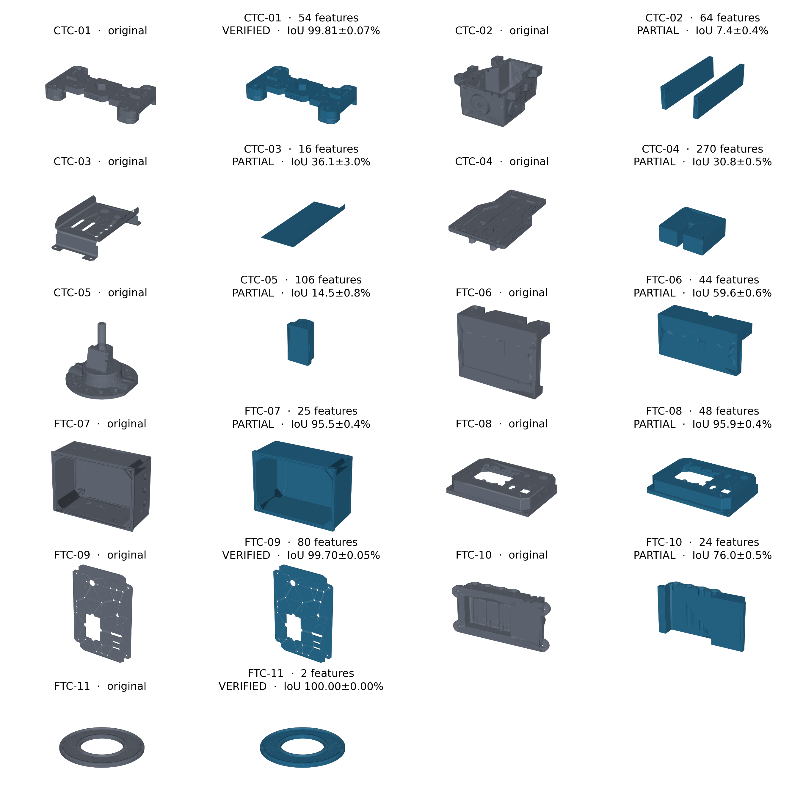
All eleven, each recovery placed exactly where its IoU was measured. The picture makes the verdicts legible in a way the numbers don't. VERIFIED means indistinguishable. PARTIAL ranges from "nearly all of it" (FTC-07, a drafted box, and FTC-08, a pan) to "a plate". CTC-04 shows why volume alone is not a test: it is within 2.43% on volume, and it is plainly the wrong shape.
| Published by NIST, not run | NIST set | Why |
|---|---|---|
| STC-06 | Simplified | same geometry as FTC-06 (confirmed: volume and extents) |
| STC-07 | Simplified | same geometry as FTC-07 per NIST; does not import in OpenCASCADE |
| STC-08 | Simplified | same geometry as FTC-08 (confirmed: volume and extents) |
| STC-09 | Simplified | same geometry as FTC-09 (confirmed: volume and extents) |
| STC-10 | Simplified | same geometry as FTC-10 (confirmed: volume and extents) |
| FTC-08 (tessellated) | Fully-toleranced | faceted surfaces, not exact B-rep; out of scope |
| HTC | Hole | 2024 model, not in the corpus download used; not evaluated |
| MTC | Modified | 2018 model, not in the corpus download used; not evaluated |
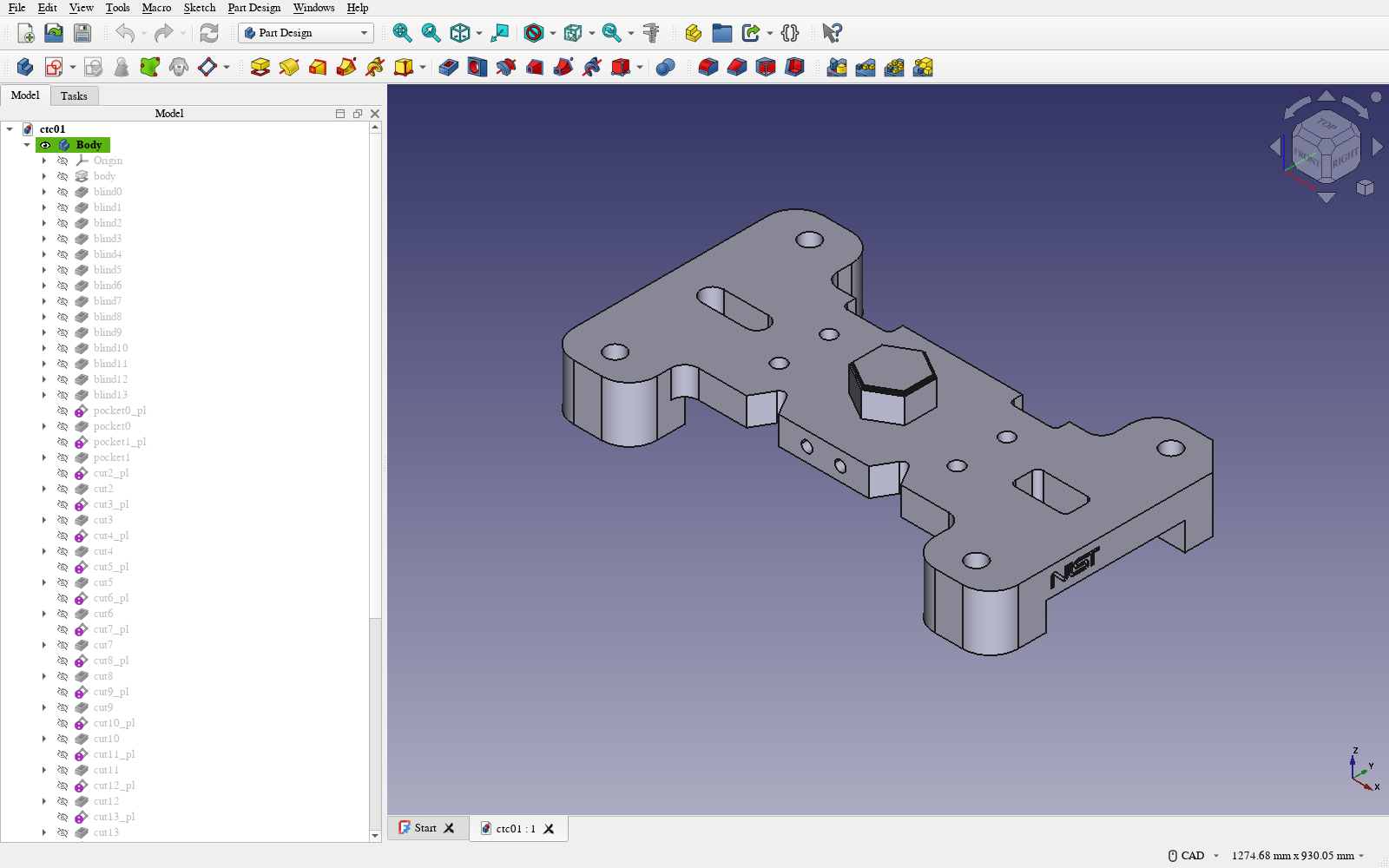
This is what VERIFIED means in practice. NIST CTC-01 is shown as a native FreeCAD Part Design document, built from the recovered tree. Every entry in the Model panel is a real, editable operation: the base extrude, fourteen blind holes, then pockets and cuts, each with its own placement sketch. Change a depth and the part rebuilds. FreeCAD's volume for this tree matches build123d's to within 0.3 mm³. Feature names are generated, not the designer's, because recognition recovers an equivalent history, not the history.
Getting the whole corpus through
The first full run refused three of the eleven parts outright: CTC-02, FTC-07 and FTC-10. Those refusals looked principled, since those are the ugly parts, full of threads and blends. They weren't. They came from two conservative choices in the front end, not from the limits of the feature vocabulary.
The first was the axis prefilter. Candidate axes with more than 40% non-conforming faces were thrown away before anything else happened. FTC-07 and FTC-10 carry modelled thread and blend geometry; their best axes score 55.0% and 47.7%, and the offending faces are almost entirely tori, cones and spheres. They were rejected before their cross-section was ever looked at. The threshold was measuring the presence of thread geometry, not the absence of a prismatic profile. CTC-02 failed at the next step: every sampled cross-section landed in a tapered region whose outline is ellipses and hyperbolas, the signature of slicing a cone off-axis.
The second was the cross-section. A section that splits into separate regions at every height was treated as a failure. A disjoint section does describe some parts correctly, as several parallel prisms that one sketch and pad per region recovers exactly. The IR could already express that; the recogniser never tried. We raised the prefilter to 75% and added the multi-region path:
| First full run | After the threshold change | |
|---|---|---|
| VERIFIED | 3 | 3 |
| PARTIAL | 5 | 8 |
| REFUSED | 3 | 0 |
| FTC-08 volume error | 52.6% | 32.6% |
Loosening a heuristic was safe because acceptance is a separate stage, not because we got lucky. The rebuild-and-compare check never sees the prefilter threshold. So loosening it can only move a part from refused to PARTIAL or VERIFIED; it cannot create a false accept. That is the practical payoff of keeping recognition and acceptance apart. The heuristics can be as aggressive as you like, and the worst case is wasted compute. Had they been one scoring function, every threshold change would have been a soundness change. No false accept appeared. FTC-08, already recovering, improved by twenty points because the wider prefilter let a better axis win. Refusal is still reachable (a torus is still refused); this corpus just doesn't exercise it.
One of those three needed more. FTC-07 looks like it should be easy: it is basically a box, an outer rectangle padded and one pocket for the cavity. The multi-region path instead recovered it as two stray walls, 63% short. The verifier reported that honestly as PARTIAL, but it's not a good answer, and the reason is how the part was being looked at.
Seeing a box as a box
No single cross-section of FTC-07 says "box". Looked at from several aspects, it can't be anything else. Across its opening, every slice is two walls. Along it, the slices are the rectangular ring an open box should give: 18 of 24 are one region with a large inner loop, solid at the floor and open at the rim. So featuretree now cuts a stack of slices along each principal axis, and an axis whose slices are mostly rings, closed at one end, is an open shell.
The slices also explained why the part was never a prism. It's a molded box, and the rings grow steadily with depth: the outer wall 1.4 mm per side over 81 mm, the cavity the same. That's 1.0° of draft on every wall, inside and out, the taper that lets a part release from its mould. featuretree didn't have draft at all, so pads and pockets now take a taper angle. FreeCAD and build123d both build it natively, and a test pins FreeCAD's sign convention against build123d's, checked by flipping it and watching the test fail. FTC-07 is then recovered as a designer would draw it: a drafted pad and a drafted cavity pocket, two operations at 87% IoU. Carving the slots and bosses takes it to 95.5%, from two walls at 30%.
The outline isn't one thing either: a straight band at the floor, the drafted wall, then a rim lip. So the outline's size against depth is split into layers wherever it stops following a straight line, and each layer becomes a pad stacked on the one below. That brought FTC-07's volume error to 0.09%, inside the gate. It stays PARTIAL, correctly, on extents alone: the rim flares to 311.6 mm at its very edge, 1.5 mm wider than the lip layer. Getting it right also exposed a latent bug in the carving step. It lined the part up against its rebuilt base by matching bounding-box corners, which is only right when the base spans the part's full extent. FTC-07's rim lip overhangs its walls by 3.18 mm, so every carved feature had landed 3.18 mm off. Fixing it moved FTC-07 from 92% to 95%; no other part's result changed.
FTC-08 is the same problem the other way up. It came back as two L-brackets, 53% IoU, but it's a shallow pan that opens downward: a 10 mm flange at the open end, straight walls, and a 3.4 mm floor with 21 cutouts. The shell detector had found it along its depth, but one straight-line fit across the flange step read as an 8° "draft", and the result lost to the L-brackets. With layers it's a flange pad, a wall pad and a cavity pocket, and the floor slice hands over its 21 cutouts directly as inner loops: 3.6% short on volume, 96% IoU. Carving then over-cut it badly, which the rebuild check rejected in favour of the uncarved pan. A guard on individual carve steps is still owed; FTC-10 needs it too.
Measuring it honestly
The recogniser's own verdicts held up. The code measuring them was less trustworthy. Scoring the PARTIAL recoveries at all, which the first harness didn't do, surfaced a run of evaluation bugs:
- Volume is a one-sided test. Over-cut and uncut material enter a volume difference with opposite signs and partly cancel. On CTC-01 the size of that cancellation moved from 1.56× to 1.01× between two versions of the recogniser, under a change not aimed at it. Nothing in a volume criterion bounds that term. IoU does not cancel, which is why the table reports it.
- Half a recovery. A helper scored only the first solid of each reconstruction, so the multi-region parts were measured on one wall. The rendering caught it: FTC-07 drew as a single plate.
- OpenCASCADE crashes. One bad Boolean killed a whole part's measurement, and one segfaulted the process outright. Every part is now measured in its own process, and a failed orientation costs only itself.
- Booleans that return the wrong answer plausibly. This one matters most. IoU was first computed from an OpenCASCADE union. When the renders were drawn, FTC-10's recovery sat at right angles to its original under a caption claiming 74% overlap; recomputed, it was about 1%. On CTC-03 the error had a clean signature. The "union" came back equal to the larger operand, so IoU collapsed to the ratio of the two volumes and passed every range check with equality. Four of the eight PARTIAL figures were wrong this way.
So featuretree now measures IoU with no Boolean operations at all. It classifies 60,000 random points against both solids and reports a 95% interval. The check ships in the library as iou_check.py, with its own tests, and on the command line as step_recognize.py part.step --iou. On CTC-01 it reads 99.81% ± 0.07. The three VERIFIED figures agree with the Boolean ones, as they must for near-identical solids; the PARTIAL ones are where the Booleans failed. The takeaway is narrower than "never use Booleans," but it is sharp. A Boolean-derived metric is safe to report only where something independent has confirmed it, and it is least safe on the recoveries that failed, which are exactly the ones you are trying to measure.
The measurement is exact, not a best guess. featuretree works in the part's own frame, rotating the extrude axis onto Z, so a recovery is generally turned relative to its input. The first harness found the alignment by trying 24 orientations and lining up bounding-box corners, which could only ever give a lower bound, and a loose one: a rim lip or a missing flange shifts the corners. The recogniser now reports the exact rotation and offset it applied, and undoing them gives a true measurement. The old bounds understated most PARTIAL parts, some badly: FTC-10 was "at least 46%" and is 76%, and CTC-03 was "at least 6.5%" and is 36%. (FTC-08's bound happened to be tight.) The preprint's second version reported Boolean IoU for the PARTIAL parts; the figures here supersede it.
Design intent, checked against the designer's drawing
A VERIFIED tree rebuilds the part, but it reads like a machine wrote it. Holes are arcs inside generic pockets, equal holes are unrelated, and every size is a bare float. So featuretree now re-expresses the tree the way a designer would have drawn it: holes as holes (a revolve's bore counts), counterbores, patterns such as bolt circles, equally spaced lines and rectangles, the unit system, and the standard size each hole most plausibly is. Because it never changes geometry, it can't break a VERIFIED tree.
NIST's AP242 files make this measurable. They carry semantic PMI: every dimension, tolerance and datum, linked to the faces it applies to. That is the designer's stated intent in machine-readable form, so the inference can be scored:
| Part | Holes found | Nominal sizes | Units | Hole grouping (P / R) |
|---|---|---|---|---|
| CTC-01 | 7/7 | 7/7 | metric ✓ | — |
| FTC-09 | 29/30 | 27/27 | inch ✓ | 0.78 / 0.78 |
| FTC-11 | 2/2 | 2/2 | metric ✓ | — |
38 of 39 dimensioned holes come back, all 36 inferred sizes agree with the drawing, and the unit system is right on all three. FTC-09 is an inch part, and its holes come back as the drills a machinist would reach for: a 5/32" drill where the drawing says .156", letter drills A and K where it says .234" and .281". Grouping is scored only on FTC-09, because NIST's Combined parts "are not intended to be fully toleranced" and their drawings never group holes. Even there, a callout group is a stand-in for pattern truth, not the truth: a designer can dimension two holes of one pattern separately. It runs as step_recognize.py part.step --intent.
Limits
- Eleven parts. That demonstrates the contract on hard, standard geometry. It is not a success rate for parts in general.
- The vocabulary is prismatic and revolved. Fillets and chamfers are left as small residuals, so a chamfered part can verify with sharp edges in its tree. Additive bosses, lofts, sweeps, freeform surfaces, and outlines with splines or ellipses come back PARTIAL. Draft is recovered on open shells but not yet elsewhere (a drafted boss), and the Onshape backend doesn't emit it.
- One small curve can lose a whole axis. FTC-10 is a 31 mm plate, and its natural extrude direction is refused because of a single 1.8 mm conic edge, where the section cuts a small cone. It deviates from a straight line by 0.09 mm. Accepting such edges as chords unlocks the axis, and the base extrude becomes a proper envelope, 53% over. But carving then over-cuts to 68% short, because nothing checks an individual carve step against the part; only the final rebuild is checked, and it correctly rejects the result. FTC-10 needs both fixes, and CTC-01 needed neither. That, not the part's orientation in the file, is why one verifies and the other doesn't.
- Equivalence, not intent. A VERIFIED tree rebuilds the part; it is not the designer's history, and its feature names are generated.
- Intent is holes, patterns, sizes and units so far. Datums and intent beyond holes aren't inferred, and it's scored on three parts.
- Not yet run: NIST's Hole and Modified test cases.
Code is at punkfab/featuretree, MIT. The paper, with the prior-art scan behind its deliberate lack of a novelty claim, is at 10.5281/zenodo.22848792. Every number and image here regenerates from the commands in paper/figures/README.md.